

- 6.10 MB
- 2021-10-12 发布
- 1、本文档由用户上传,淘文库整理发布,可阅读全部内容。
- 2、本文档内容版权归属内容提供方,所产生的收益全部归内容提供方所有。如果您对本文有版权争议,请立即联系网站客服。
- 3、本文档由用户上传,本站不保证质量和数量令人满意,可能有诸多瑕疵,付费之前,请仔细阅读内容确认后进行付费下载。
- 网站客服QQ:403074932
1
高电压与绝缘技术的发展
高电压与绝缘技术的主要内容
高电压新技术及其在各领域的应用
第五章 高电压与绝缘技术
2
一、高电压与绝缘技术的发展
◇
高电压与绝缘技术是以
试验研究
为基础的应用技术,主要研究在高电压作用下
各种绝缘介质的性能和不同类型的放电现象
,
高电压设备的绝缘结构设计
,高电压
实验和测量的设备及方法
,
电力系统的过电压
、高电压或大电流产生的
强电场、强磁场
或电磁波对环境的影响和防护措施,以及
高电压、大电流的应用
等。
◇
高电压技术对电力工业、电工制造业以及近代物理的发展(如
X
射线装置、粒子加速器、大功率脉冲发生器等)都有重大影响。
3
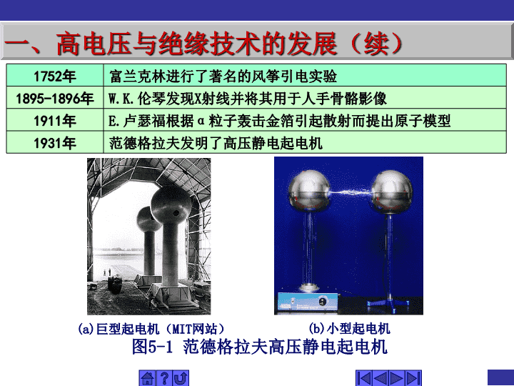
1752
年
富兰克林进行了著名的风筝引电实验
1895-1896
年
W.K.
伦琴发现
X
射线并将其用于人手骨骼影像
1911
年
E.
卢瑟福根据
α
粒子轰击金箔引起散射而提出原子模型
1931
年
范德格拉夫发明了高压静电起电机
(a)
巨型起电机(
MIT
网站)
(b)
小型起电机
图
5-1
范德格拉夫高压静电起电机
一、高电压与绝缘技术的发展(续)
4
◇
高电压是相对于低电压而言的,对于电力系统来说,
1kV
以上至
220kV
称为高压
,
220kV
至
800kV
称为超高压(
EHV
)
,
1000kV
以上称为特高压(
UHV
)
。
◇
绝缘体是相对于导体而言的,绝缘体电阻率很高(可达
10
9
~
10
22
Ω
.
cm
),通常通过的泄漏电流非常小,可以忽略不计。
一、高电压与绝缘技术的发展(续)
5
一、高电压与绝缘技术的发展(续)
7
二、高电压与绝缘技术的主要内容
◇
研究高电压的产生,在高电压下绝缘介质及其系统的特性,电气设备及绝缘,电气系统过电压及其限制措施,高电压试验技术,电磁环境及电磁污染防护,以及高电压技术的应用等。
◇
主要内容可分为四部分:
①
各类电介质在高电场下的特性
(
图
5-3)
;
②
电气设备绝缘试验技术
;
③
电力系统过电压与绝缘配合
;
④
高电压技术在
各个领域的应用等。
8
图
5-3
实验室产生的高压放电现象
二、高电压与绝缘技术的主要内容(续)
9
二、高电压与绝缘技术的主要内容(续)
1
、
高电压的产生
雷电
:电流达
100kA
,电压达
10
8
kV
,但持续时间短。
雷电放电过程
雷电放电过程
雷电参数
雷电活动强度
——
雷暴日及雷暴小时
雷暴日
:每年中有雷电的天数。
雷暴小时
:每年中有雷电的小时数。
年平均雷暴日不超过
15
的地区为
少雷区
;超过
40
的为
多雷区
;超过
90
的地区及根据运行经验雷害特别严重的地区为
强雷区
。
落雷密度
地面落雷密度
γ
:每一个雷暴日、每平方公里对地面落雷次数 。
静电
:放电脉冲上升时间约为
1~5ns
,脉宽
150ns
,电流峰值约
1~50A
。
高压发生装置
:
交流
高电压发生装置,
直流
高电压发生装置,
冲击电压电流
发生装置。 (图
5-5
,
5-6
)。
13
二、高电压与绝缘技术的主要内容(续)
图
5-5
户外式高压发生装置
R
R
R
R
多级冲击电压发生器
R
f
R
t
AT
T
(
1
)充电过程:
由试验变压器
T
和高压硅堆
D
构成的整流电源,以峰值电压经保护电阻及充电电阻向主电容充电。
(
2
)放电过程:
当需要启动冲击电压发生器时,可向点火球隙的针极送去一脉冲电压,针极和球表面之间产生火花放电,引起点火球隙放电,各球隙相继放电,将电容器串联起来,对试品放电。
“
电容器并联充电,串联放电
”
,这一过程由一组球隙来完成。
16
二、高电压与绝缘技术的主要内容(续)
图
5-6 6000kV
冲击电压发生器(中国电力科学院)
17
2
、
高电压绝缘与电气设备
绝缘材料:
气体,液体,固体
(有机,无机)
高电压技术发展的关键是绝缘材料的研制和开发
研究重点:
①
高压大容量发电机的环氧粉云母绝缘体系;
②
中小型电机的
F
、
H
级绝缘系列;
③
高压输电的六氟化硫气态介质;
④
高性能绝缘油。
二、高电压与绝缘技术的主要内容(续)
18
电机为了可靠运行在带电部件和壳体之间需要用绝缘材料加以隔绝,而绝缘材料的使用寿命与其材料本身的绝缘等级及使用温度有很大的关系。
电机的绝缘等级是依据所用国内绝缘材料的耐热等级划分的,分
E
、
B
、
F
、
H
级。允许温升是指电机的温度与周围环境温度相比升高的限度。
绝缘等级
使用极限温度
温升限值
E
120℃
75K
B
130℃
80K
F
155℃
105K
H
180℃
120K
SF
6
气体已有百年历史,它是法国两位化学家
Moissan
和
Lebeau
于
1900
年合成的人造惰性气体,
1940
年前后,美国军方将其用于曼哈顿计划(核军事)。
1947
年提供商用。当前
SF
6
气体主要用于电力工业中。
SF6
气体用于
4
种类型的电气设备作为绝缘和
/
或灭弧
:SF
6
断路器及负荷开关设备,
SF6
绝缘输电管线,
SF
6
变压器及
SF
6
绝缘变电站。
80
%用于高中压电力设备。
SF
6
气体主要有如下特性:
具有优异的灭弧性能;
绝缘强度高,在大气压下为空气的
3
倍;
热传导性能好且易复合,特别是当
SF6
气体由于放电或电弧作用出现离解时;
可在小的气罐内储存,这是因为室温下加高压力易液化。
供气方便,价格不贵且稳定
。
19
20
电气设备的绝缘:
①
发电机绕组
通常采用环氧粉云母带做绝缘;
②
变压器
采用油
-
纸,树脂和六氟化硫等;
③
断路器
采用空气,油,和六氟化硫等;
④
电容型设备采用套管和油
-
纸等绝缘;
⑤
架空输电线路
--
绝缘子和
分裂导线
;
⑥
地下输电线路
--
电力电缆;
⑦
气体绝缘金属封闭组合电器
(图
5-7
)。
21
22
二、高电压与绝缘技术的主要内容(续)
图
5-7
气体绝缘金属封闭组合电器
(
1
)节省占用面积和空间;
(
2
)性能好,运行安全可靠
(
3
)不产生噪声和干扰
(
4
)安装工期短,
维护工作量小
24
3
、
高电压试验技术
随着电力系统电压等级的不断提高,绝缘成为电气设备中
的薄弱环节。高电压试验是研究击穿机理、影响因素、电气
强度以及检验电气设备耐受水平的最好方法。
介质绝缘强度
电气设备绝缘试验:
集中性缺陷
——
发展速度快
1
、绝缘缺陷
:
分布性缺陷
——
演变速度慢
2
、试验方法分为两类:非破坏性试验和破坏性试验。
二、高电压与绝缘技术的主要内容(续)
非破坏性试验:在较低电压下或其他不会损坏绝缘的方法来检测绝缘,判断绝缘状态,及时发现可能的劣化现象。
绝缘电阻测量
——
兆欧表;
直流泄漏电流测量
;
介质损失(损耗)角测量
——
西林电桥;
局部放电测量
。
25
绝缘电阻
绝缘电阻是一切电介质和绝缘结构的绝缘状态最基本的综合性特性参数
。由于电气设备中大多采用组合绝缘和层式结构,故在直流电压下均会有明显的吸收现象,使外电路中出现一个随时间而衰减的吸收电流。
绝缘电阻测量
——
兆欧表
对于不均匀试品的绝缘,如果绝缘状况良好,则吸收现象明显,值远大于
1
;如果绝缘严重受潮,由于
I
g
大增,
I
a
迅速衰减,
K
a
值接近于
1
。
测量绝缘电阻能有效地发现下列缺陷:
总体绝缘质量欠佳;绝缘受潮;两极间有贯穿性的导电通道;绝缘表面情况不良
。测量绝缘电阻不能发现下列缺陷:
绝缘中的局部缺陷:如非贯穿性的局部损伤、含有气泡、分层脱开等;绝缘的老化。
不论是绝缘电阻的绝对值或是吸收比都只是参考性的。如不满足最低合格值,则绝缘中肯定存在某种缺陷;但是,如已满足最低合格值,也还不能肯定绝缘是良好的。有些绝缘,特别是油浸的或电压等级较高的绝缘,即使有严重缺陷,用兆欧表测得的绝缘电阻值、吸收比,仍可能满足规定要求,这主要是因为兆欧表的电压较低的缘故。
测量泄漏电流从原理上来说,与测量绝缘电阻是相似的,但它所加的直流电压要高得多,能发现用兆欧表所不能显示的某些缺陷,具有自己的某些特点。
直流泄漏电流
测量泄漏电流相比测量绝缘电阻可使用较高的电压。
泄漏电流能够
发现一些尚未完全贯通的集中性缺陷。这是因为一方面加在试品上的直流电压要比兆欧表的工作电压高得多,故能发现兆欧表所不能发现的某些缺陷,另一方面,这时施加在试品上的直流电压是逐渐增大的,这样就可以在升压过程中监视泄漏电流的增长动向。
泄漏电流的测量
32
直流泄漏电流测量
某设备绝缘的泄漏电流曲线
曲线
1
:绝缘良好;曲线
2
:绝缘受潮;
曲线
3
:绝缘中有未贯通的集中性缺陷;
曲线
4
:绝缘有击穿的危险
发电机的泄漏电流变化曲线
绝缘良好的发电机,泄漏电流值较小,且随电压呈线性上升,如曲线
1
所示;如果绝缘受潮,电流值变大,但基本上仍随电压线性上升,如曲线
2
所示;
曲线
3
表示绝缘中已有集中性缺陷,应尽可能找出原因加以消除;如果在电压尚未到直流耐压试验电压 的
1
/
2
时,泄漏电流就已急剧上升,
如曲线
4
所示,那么这台发电机在运行电压下
(
不必出现过电压
)
就可能会发生击穿。
发电机的泄漏电流变化曲线
局部放电测量
37
介质损失(损耗)角
39
介质损失(损耗)角测量
电气工程专业导论
40
西林电桥的基本原理
破坏性试验:在各种较高电压下进行的试验,也称为耐压试验。目的在于考核绝缘的电气强度
雷电冲击耐压试验;
交、直流耐压试验;
操作冲击耐压试验。
42
43
45
二、高电压与绝缘技术的主要内容(续)
高电压试验设备
图
5-9
高电压分压器
分压器是高电压试验中必备的测量设备,它能将高电压转换为可用普通电压表测量的安全低电压。其测量准确性、直观性及使用方便性是传统测量高电压采用的静电电压表、测量球隙等所无法比拟的。
分压器一般是指不带测量仪表的“分压器体”,如配有普通电压表、专用电压表、多功能峰值表或记录仪等,则可称为:高压分压器测量系统、千伏表等。
2.
电容分压器
C
2
C
1
U
1
U
2
交流电容分压器
分压器
高压臂
分压器
低压臂
分压器的分压比是常数,即不应随被测电压的波形、频率、幅值、周围大气条件、安装地点的变化而改变。此外,分压器的接入应不影响电压波形和幅值。
(
1
)分布式电容分压器
,它的高压臂有多个电容器元件串联组装而成,要求每个元件尽可能为纯电容,介质损耗和电感尽可能小。
(
2
)集中式电容分压器
,它的高压臂使用一个气体介质的高压标准电容器。
对于电容分压器低压臂电容
C2
,要求电容量较大而承受的电压较低,因此应采用高稳定度、低损耗、低电感量的云母、聚苯乙烯等介质的电容器。
电容量根据分压比和低压仪表的量程确定。
47
图
5-11
高压试验变压器
作用
1
、产生工频高压试验电压
2
、作为直流高压和冲击高压设备的电源变压器
3
、产生操作波试验电压
特点
与一般电力变压器比较,试验变压器有以下特点:
(
1
)变压器的容量不大
(
2
)变压器一般为单相油浸式
(
3
)由于变压器连续工作时间短,不需要散热装置(
4
)绝缘裕度较低,不需考虑变压器受大气或内部过电压的影响
(
5
)工频输出电压高,可达到几百到几千
KV
48
二、高电压与绝缘技术的主要内容(续)
图
5-12
数字式局部放电检测系统
图
5-13
通用型钳形表
49
二、高电压与绝缘技术的主要内容(续)
电气设备诊断及在线监测
对电气设备进行试验和各种特性测量,了解其特征,评估设备状态,及时发现故障,称为电气设备诊断技术(
Diagnostic Technique
)
50
二、高电压与绝缘技术的主要内容(续)
4
、
电力系统过电压及其保护
电力系统过电压
雷电(大气)过电压
内部过电压
暂态过电压
操作过电压
直击雷过电压
感应雷过电压
工频过电压
谐振过电压
常用过电压限制措施:
装避雷针、避雷器,调整线路参数,装设并联电抗器、静止无功补偿器,在操作断路器触头上装设并联电阻,以及用快速继电保护减小工频电压升高及其持续时间等。
工频过电压
工频过电压在暂时过电压中的重要性:它是确定超高压远距离输变电设备绝缘水平的重要依据,其幅值影响保护电器的工作条件和保护效果。它的持续时间影响设备绝缘及运行性能,并且长线中的操作过电压是在工频过电压的基础上振荡产生的。在超高压输电系统中,工频电压升高应当受到相当的重视。
产生原因:长线电容效应、不对称接地和突然甩负载。
采取措施:传统的方法是使用同步补偿机或并联电抗器,近年来的发展了静止无功补偿技术,各有优缺点。
51
谐振过电压
一、产生谐振过电压的原因:由于系统中存在着大量的电容电感元件,在系统进行操作或发生故障时,这些电容电感元件可能形成各种不同自振频率的振荡回路,在外电源的作用下发生谐振现象,造成某些元件上出现谐振过电压。
二、谐振过电压的特点:是一种稳态现象,存在的时间较长,对电气设备绝缘的危害大。
三、谐振的类型:由于系统中的电阻电容元件可以认为是线性的,而电感则可能是线性的、非线性的或作周期性变化的,按电感的类型不同,谐振分为
1
、线性谐振
2
、参数谐振
3
、铁磁谐振
52
操作过电压
1
、产生:系统中对断路器的操作而带来的过电压。
其过电压倍数
K
的大小和持续时间与电网的结构,断路器的性能,系统的接线方式及运行操作方式有关。
K
一般为
3
~
4
2
、类型:
(
1
)空载线路合闸过电压
(
2
)切除空载线路过电压
(
3
)切除空载变压器过电压
(
4
)中性点不接地系统中弧光过电压
54
56
57
58
二、高电压与绝缘技术的主要内容(续)
5
、
防雷及防雷设备
避雷针与避雷器
图
5-14
氧化锌避雷器
59
三、高电压新技术及其在各领域的应用
1
、
等离子体技术
2
、
激光
3
、
液电效应
4
、
静电技术及其应用
5
、
环保应用
6
、
在材料、冶金及加工中的应用
7
、
在照明技术中的应用
60
Thank you
!
That's all
61
5.1
Development of High Voltage and Insulation Technology
5.2
Main Contents of High Voltage and Insulation Technology
5.3
High Voltage New Technology and Application in Various Fields
Chapter5 High Voltage and Insulation Technology
62
5.1
Development of High Voltage and
Insulation Technology
◇
High voltage and insulation technology
is an application technology basing
on experiment research
. It studies the performance of insulation medium and different types of discharge phenomena, insulation structure design of high voltage equipment, the devices and methods of high voltage experiment and measurement, the effects of highfield, intense magnetic field, and electromagnetic field producing by over voltage, high voltage and large current of power system, and protective measures on environment, the application of high voltage and large current, etc.
◇
High voltage technology has great effects on power industry, electrotechnical manufacturing industry and the development of modern physics (e.g. X ray device, particle accelerator and large power pulse generator, etc).
63
5.1
Development of High Voltage and
Insulation Technology
1752
Franklin made the famous kite electrical penetration experiment
1895-1896
Roentgen discovered X ray and used it in hand skeleton image
1911
E.Rutherford introduced atom model according to scattering caused by
α
particle bombarding the golden foil
1931
Van de Graaff invented high voltage electrostatic electrifier
(a) Giant electrifier
(
MIT
web
)
(b) Small electrifier
Fig.5-1 Van de Graaff high voltage electrostatic electrifier
64
5.1
Development of High Voltage and
Insulation Technology
◇
High voltage is a comparative value. To power system, high voltage is between 1kV and 220kV, extra high voltage (EHV) is between 220kV
and 800kV, ultra high voltage (UHV)
is greater than 1000kV.
◇
Insulator is corresponding with conductor. The resistivity is very high (10
9
~10
22
Ω
.cm), and the passed leakage current is so small that can be neglected.
65
5.1
Development of High Voltage and
Insulation Technology
As a technology science closely related to national economy, the high voltage technology develops with the need of distribution project and high voltage equipments.
In 1891, Germany built the 175km long, 15.2kV three-phase AC distribution line. Though the delivered power was only 200kW, it began the application in distribution project of high voltage technology.
Fig 5-2 High voltage power transmission
66
5.2
Main Contents of High Voltage and
Insulation Technology
◇
Study the generation of high voltage, the performance of insulation medium and its system in high voltage, electrical equipment and insulation, over voltage and restriction measurement in electric system, high voltage test technique, electromagnetic environment and electromagnetic pollution protection, application of high voltage technology, etc.
◇
Main contents:
①
Characteristics of various electric mediums in highfield;
②
Electric equipment insulation test technology;
③
The over voltage and insulation coordination in power
system;
④
Application of high voltage technology in various fields.
67
5.2
Main Contents of High Voltage and
Insulation Technology
Fig 5-3 High voltage discharge in laboratory
68
5.2
Main Contents of High Voltage and
Insulation Technology
1.
The generation of high voltage
Thunderstorm electricity
:
current can be 100kA, voltage can be 10
8
kV, short duration time.
Electrostatic
:
the rising time of discharge pulse is about 1~5ns, pulse width is 150ns, current peak current is about 1~50A. (Fig 5-4)
High voltage generation device
: AC high voltage generation device, DC high voltage generation device, impulse voltage or current generation device. (Fig 5-5, 5-6)
69
5.2
Main Contents of High Voltage and
Insulation Technology
Fig 5-4 High voltage electrostatic
70
5.2
Main Contents of High Voltage and
Insulation Technology
Fig 5-5 Outdoor high voltage generation device
71
5.2
Main Contents of High Voltage and
Insulation Technology
Fig 5-6 6000kV impulse voltage generator
72
5.2
Main Contents of High Voltage and
Insulation Technology
2.
High voltage insulation and electric equipment
Insulation materials:
gas, liquid, solid (organic, inorganic);
Key point of high voltage technology development:
research and development of insulation materials
;
The insulation of electric equipment:
①Generator: epoxy micapaper tape;
②
Transformer: oil-paper, resin, SF
6
, etc;
③
Circuit breaker: air, oil, SF
6
, etc;
④
Capacitive equipment: casing and oil-paper, etc;
⑤
Overhead transmission line: insulator;
⑥
Underground transmission line: power cable;
⑦
Gas lnsulated Switchgear
----
GIS
(Fig 5-7).
73
5.2
Main Contents of High Voltage and
Insulation Technology
Fig 5-7 GIS
74
5.2
Main Contents of High Voltage and
Insulation Technology
3.
High voltage test technology
With the increase of the voltage level in power system, insulation becomes a weak link in electric equipment. High voltage test is the best way to study the puncture principle, influencing factors, electric intensity and the duration level of electric equipment.
Medium insulation intensity
Electric equipment insulation test
Test methods: non-destructive test and destructive test.
Main contents of test:
①
The measurement of insulation resistance and absorptance;
②
The measurement of leakage current;
③
The measurement of partial discharge;
④
Color spectrum analysis of insulating oil;
⑤
Line-frequency AC withstand voltage test;
⑥
DC withstand voltage test;
⑦
Impulse high voltage test;
⑧
Online monitoring technique of electric equipment, etc.
75
5.2
Main Contents of High Voltage and
Insulation Technology
Fig 5-8 Ball-gap discharge test
76
5.2
Main Contents of High Voltage and
Insulation Technology
High voltage test equipment
Fig 5-9 High voltage bleeder
Fig 5-11 High voltage testing transformer
Fig 5-10 High voltage voltmeter
77
5.2
Main Contents of High Voltage and
Insulation Technology
Fig 5-12 Digital partial discharge testing system
Fig 5-13 General clip-on meter
78
5.2
Main Contents of High Voltage and
Insulation Technology
Electric equipment diagnosis and online monitoring
Electric equipment diagnostic technique: test and various characteristics measurement, understand of distinctions, evaluation of the equipment status, discovery of the failures in time.
79
5.2
Main Contents of High Voltage and
Insulation Technology
4
、
Power system over voltage and protection
Power system over voltage
Lightning (aerosphere) surge
Inner surge
Transient surge
Switching surge
Straight line thunder surge
Inductive thunder surge
Line-frequency voltage increase
Resonance surge
Standard over voltage restriction method:
Fix lightning arrester, adjust line parameters, load parallel reactor and SVC, load parallel resistance in operating circuit breaker contactor, decrease the lifting of line-frequency voltage and duration time using the rapid relay protection.
80
5.2
Main Contents of High Voltage and
Insulation Technology
5.
Lightning protection and equipment
lightning rod and lightning arrester
Fig 5-14 ZnO arrester
81
5.3
High Voltage New Technology and
Application in Various Fields
1.
Plasma technique
2.
Laser power generation
3.
Hydro-electric effect
4.
Electrostatic technique and application
5.
Environment
protection application
6.
Applications in material, metallurgy and medical
7.
Application in lightening technique
82
5.3
High Voltage New Technology and
Application in Various Fields
plasma processing technique
Textile industry
Paper manufacturing industry
Waste disposal
communication
Photology industry
Aviation industry
Defense industry
Automotive industry
Computer industry
Biological medical
Fig 5-15 Application of low temperature plasma technique
83
Thank you
!
That's all